IEEE 754 Half-Precision Floating-Point Adder
Intel MAX 10 FPGA
A 16-bit IEEE 754 floating-point adder/subtractor designed and synthesized in SystemVerilog, wrapped in a complete keypad-to-display user-facing system.
- SystemVerilog
- Intel Quartus Prime
- Static timing analysis
- Logic elements
- 706
- Registers
- 137
- Format
- FP16
- Keypad
- 4×4
- 01
Implemented operand magnitude ordering, exponent-difference mantissa alignment, sign-aware add/subtract, normalization, and overflow/underflow flags.
- 02
Built the full user-facing system: 4×4 matrix keypad scanner with FSM debounce, edge-detected operand capture, and a time-multiplexed 7-segment driver.
- 03
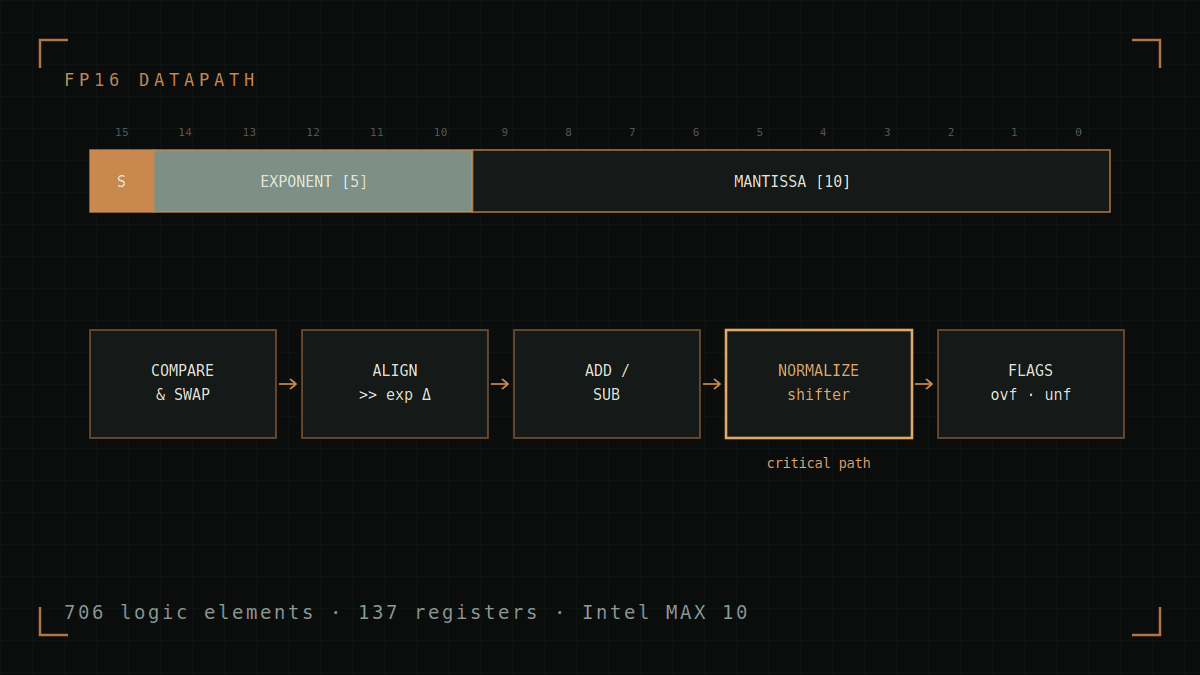
Identified the unrolled normalization shifter as the critical path from static timing results, with pipelining as the route to closure.
The datapath
Floating-point addition is mostly bookkeeping around a single integer add. Operands are ordered by magnitude so the smaller exponent is always the one shifted; the mantissa is aligned by the exponent difference; the add or subtract is selected by comparing signs; and the result is normalized back into IEEE 754 form with overflow and underflow flagged at the boundaries.
A full system, not just a block
The adder is wrapped in everything needed to actually use it on the board. A 4×4 matrix keypad is scanned with an FSM that debounces mechanical bounce and decodes hex; edge detection captures each operand exactly once per press; and a time-multiplexed driver scans the 7-segment displays fast enough to look continuous.
Timing analysis
Synthesis landed at 706 logic elements and 137 registers. Reading the static timing report, the critical path is the unrolled normalization shifter — an unavoidable consequence of doing a variable-length shift combinationally in a single cycle. Pipelining that shifter is the clear route to timing closure, trading one cycle of latency for a substantially higher fmax.